

Classic Topology — Ground-Referenced Output
Core Pulse Technology
What it is
Classic is VITAVE's single-ended output topology. One electrode switches while the other remains at ground. The potential difference between the electrodes determines the waveform the load sees.
For unipolar operation, the switching electrode goes to positive while the reference electrode stays at ground. The potential difference goes in one direction only — from the active electrode, through the load, to ground.
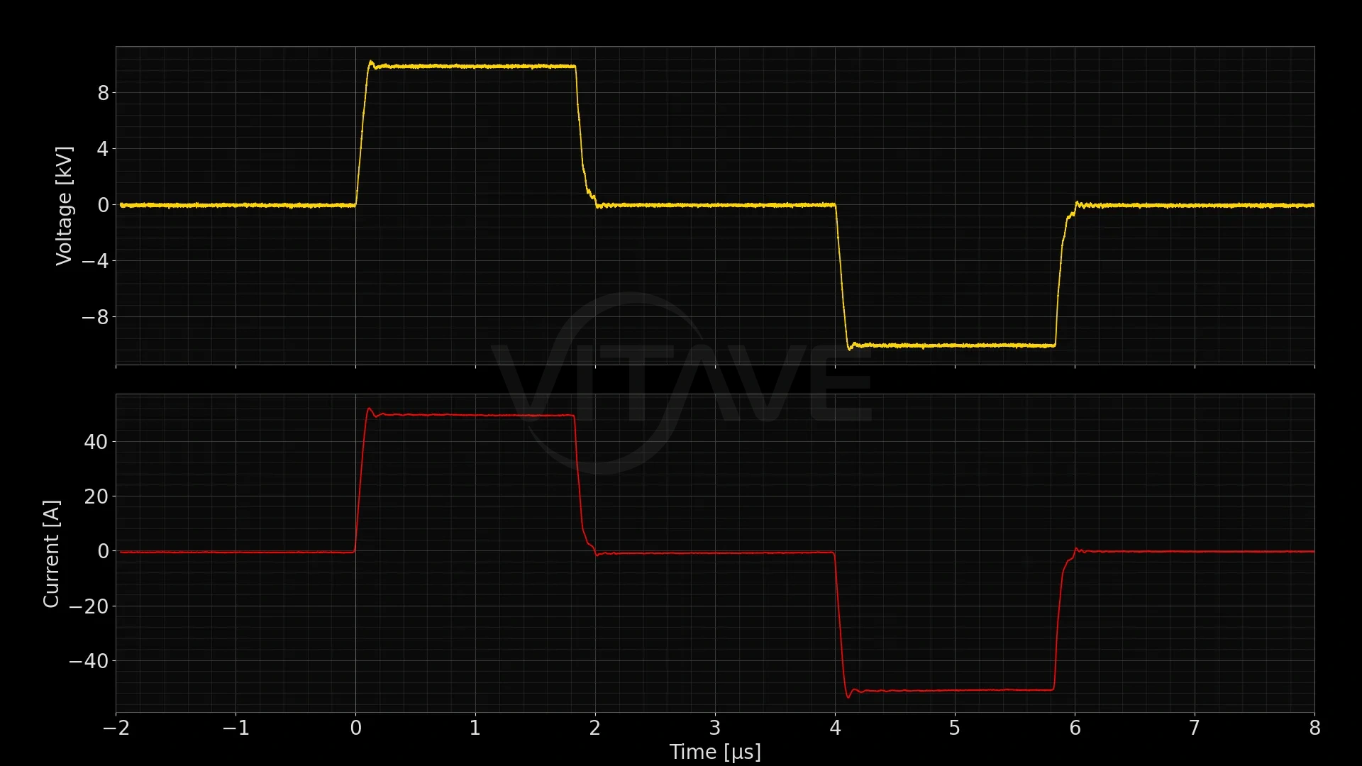
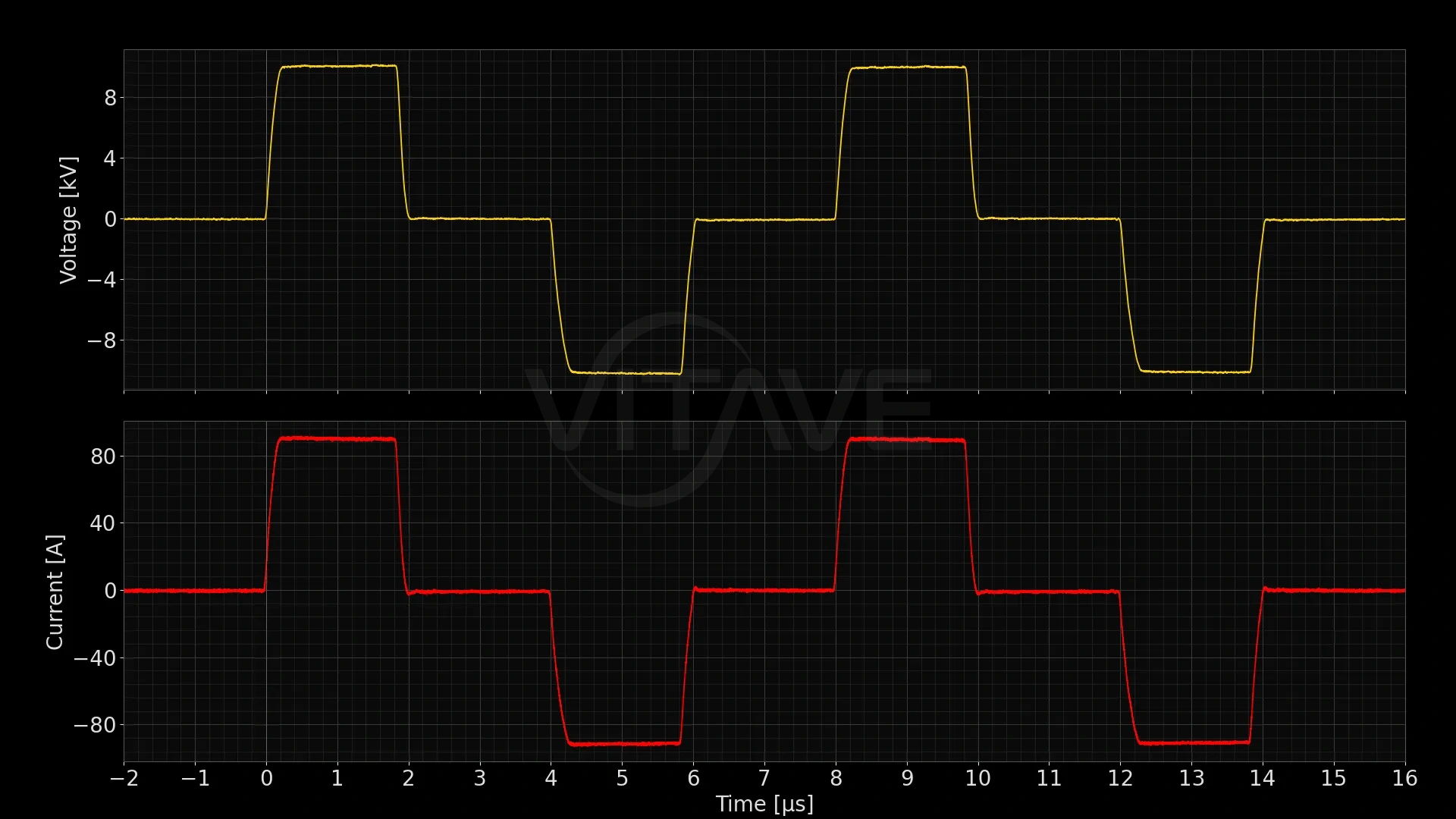
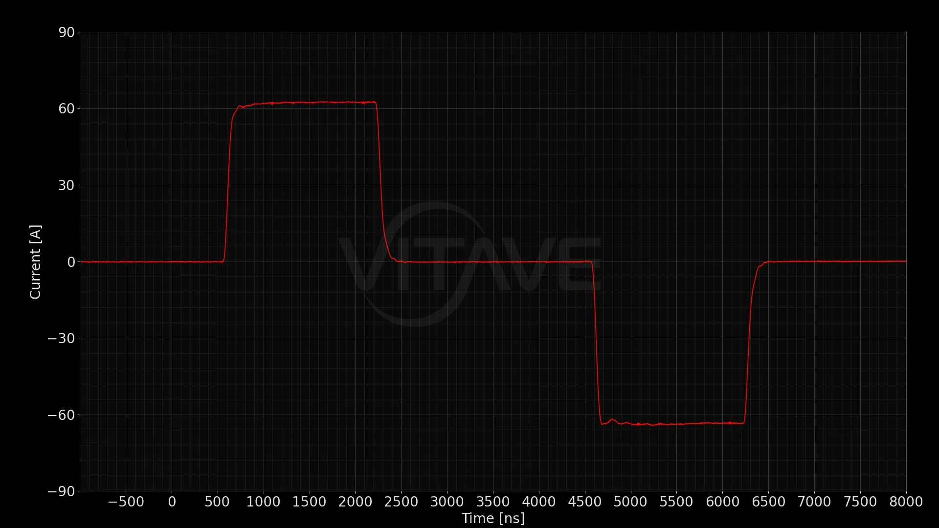
For bipolar operation, the switching electrode alternates between positive and negative — first to +HV, then after a short break to −HV — while the reference electrode remains at ground the entire time. The potential difference across the load reverses direction between pulses. The amplitude is the same in both directions: full HV.
Classic is one of three topologies available across the VITAVE platform. It is selected based on the application requirements — not priced as an upgrade, not fixed by the product line.


Why it matters
If you're replicating or building on a published protocol, there's a good chance it used Classic topology without saying so — it's the default most researchers assume. Matching it means one less variable to account for when comparing your results against the literature, and it's the safest starting point if you don't have a specific reason to choose otherwise.
If your setup requires one electrode permanently at ground — an existing safety fixture, lab grounding standards, equipment you're integrating with — Classic is the only one of the three topologies where the reference electrode stays at ground throughout, in both unipolar and bipolar operation.
Technical detail
In Classic topology, the output stage consists of one switching electrode and one reference electrode held at ground. The load is connected between them.
For unipolar operation, the switching electrode is driven to +HV. The potential difference between the electrodes is +HV. Current flows from the switching electrode through the load to ground. When the switch opens, the voltage returns to zero.
For bipolar operation, the switching electrode is driven first to +HV, then after a programmable inter-pulse delay to −HV. In the first phase, the potential difference is +HV. In the second phase, the potential difference is −HV. The amplitude is full HV in both directions. The reference electrode remains at ground throughout.
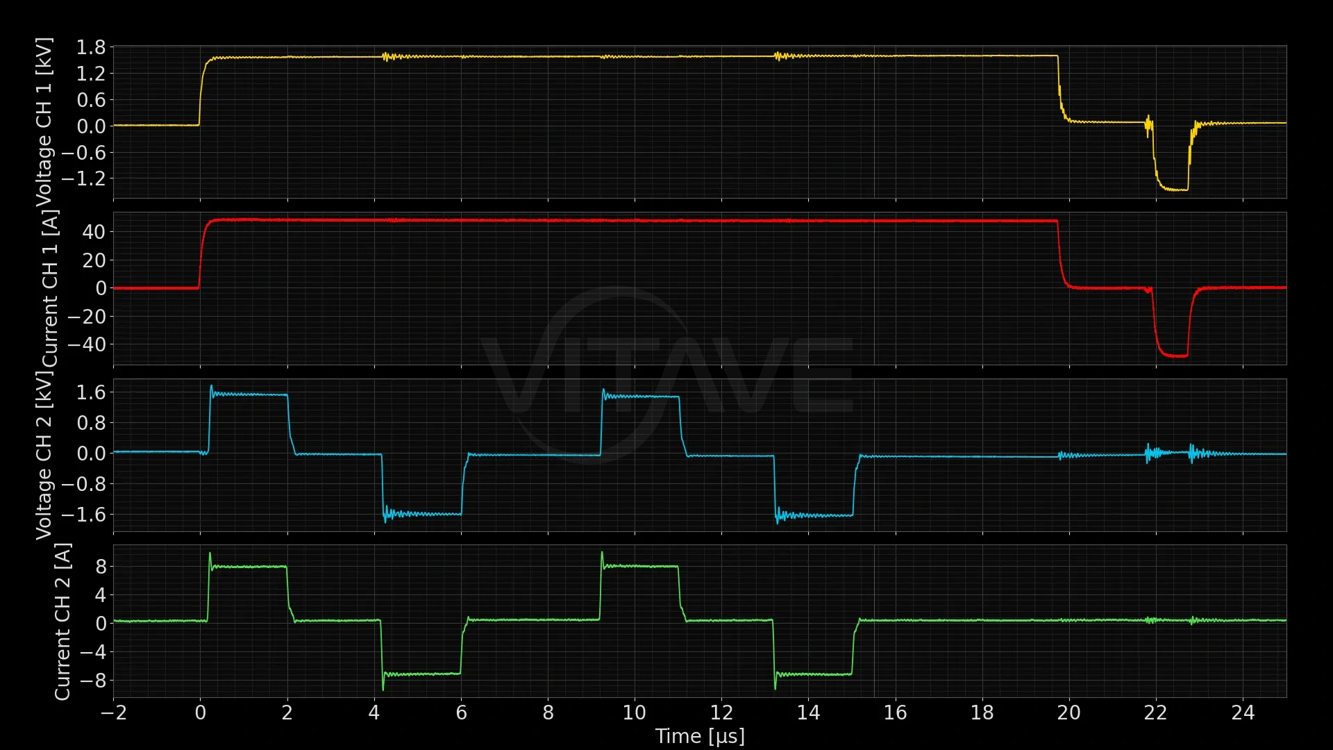
The rise time, pulse width, inter-pulse delay, and fall time are controlled by the switching signal. The bipolar pattern — alternating positive and negative with a break between — is defined in the pulse sequence.
See also